- 您现在的位置:买卖IC网 > Sheet目录310 > AL8807W5-7 (Diodes Inc)IC LED DRVR DCDC BUCK SOT25
�� �
�
�AL8807�
�Application� Information� (cont.)�
�The� following� equations� can� be� used� as� a� guide,� with� reference� to� Figure� 1� -� Operating� waveforms.�
�Switch� ‘On’� time�
�Switch� ‘Off’� time�
�t� ON� ?�
�L� ?� I�
�V� IN� ?� V� LED� ?� I� AVG� x� ?� R� S� ?� r� L� ?� R� SW� ?�
�t� OFF� ?�
�L� ?� I�
�V� LED� ?� V� D� ?� I� AVG� x� ?� R� S� ?� r� L� ?�
�Where:�
�L� is� the� coil� inductance� (H)�
�r� L� is� the� coil� resistance� (� ?� )R� S� is� the� current� sense� resistance� (� ?� )�
�I� avg� is� the� required� LED� current� (A)�
�Δ� I� is� the� coil� peak-peak� ripple� current� (A)� {Internally� set� to� 0.3� x� Iavg}�
�V� IN� is� the� supply� voltage� (V)�
�V� LED� is� the� total� LED� forward� voltage� (V)�
�R� SW� is� the� switch� resistance� (� ?� )� {=0.5� ?� nominal}�
�V� D� is� the� diode� forward� voltage� at� the� required� load� current� (V)�
�Thermal� Considerations�
�For� continuous� conduction� mode� of� operation,� the� absolute� maximum� junction� temperature� must� not� be� exceeded.� The� maximum� power� dissipation�
�depends� on� several� factors:� the� thermal� resistance� of� the� IC� package� ?� JA� ,� PCB� layout,� airflow� surrounding� the� IC,� and� difference� between� junction�
�and� ambient� temperature.�
�The� maximum� power� dissipation� can� be� calculated� using� the� following� formula:�
�P� D(MAX)� =� (T� J(MAX)� ?� T� A� )� /� ?� JA�
�where�
�T� J(MAX)� is� the� maximum� operating� junction� temperature,�
�T� A� is� the� ambient� temperature,� and�
�?� JA� is� the� junction� to� ambient� thermal� resistance.�
�The� recommended� maximum� operating� junction� temperature,� T� J� ,� is� 125°C� and� so� maximum� ambient� temperature� is� determined� by� the� AL8807’s�
�junction� to� ambient� thermal� resistance,� ?� JA� and� device� power� dissipation.�
�?� JA� ,� is� layout� dependent� and� package� dependent;� the� AL8807W5’s� ?� JA� on� a� 25x25mm� single� layer� PCB� with� 1oz� copper� standing� in� still� air� is�
�approximately� 250°C/W� (160°C/W� on� a� four-layer� PCB).�
�The� maximum� power� dissipation� at� T� A� =� 25°C� can� be� calculated� by� the� following� formulas:�
�P� D(MAX)� =� (125°C� ?� 25°C)� /� (250°C/W)� =� 0.4W� for� single-layer� PCB�
�P� D(MAX)� =� (125°C� ?� 25°C)� /� (160°C/W)� =� 0.625W� for� standard� four-layer� PCB�
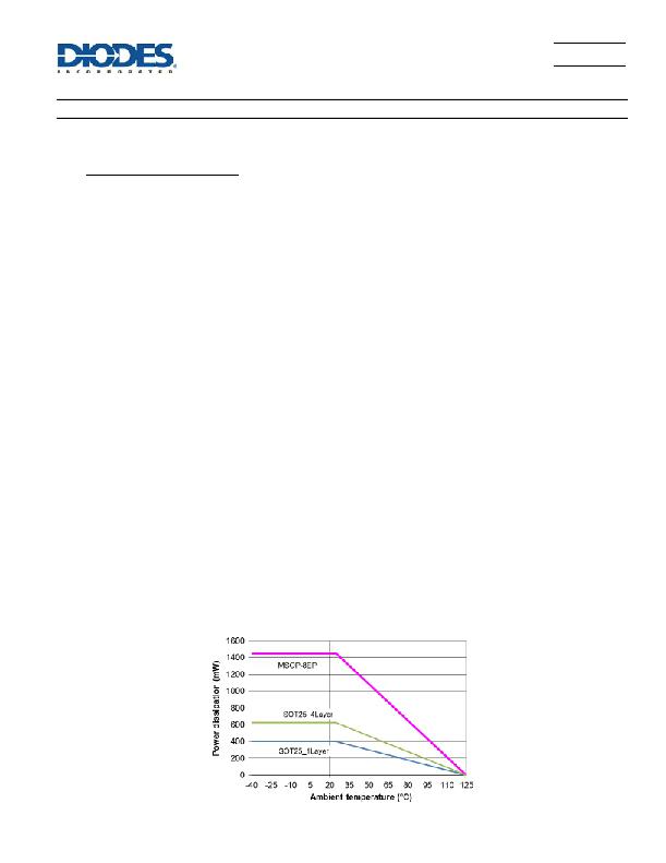
�Figure� 35,� shows� the� power� derating� of� the� AL8807W5� on� two� (one� single-layer� and� four-layer)� different� 25x25mm� PCB� with� 1oz� copper� standing� in�
�still� air� and� the� AL8807MP� on� an� FR4� 51x51mm� PCB� with� 2oz� copper� standing� in� still� air.�
�Figure� 35� Derating� Curve� for� Different� PCB�
�AL8807�
�Document� number:� DS35281� Rev.� 5� -� 2�
�13� of� 20�
�www.diodes.com�
�March� 2013�
�?� Diodes� Incorporated�
�发布紧急采购,3分钟左右您将得到回复。
相关PDF资料
AL9910AS-13
IC LED DRVR HIGH BRIGHT SO8EP
ALC60481R05
PWR SUP AC-DC 6-48V 1.05A 50.4W
ALV100362R5
POWER SUPPLY AC-DC 36V 2.5A 90W
ALV60361R7
POWER SUPPLY AC-DC 36V 1.7A 61W
ALV80126R5
POWER SUPPLY AC-DC 12V 6.5A 78W
AOZ1083CI
IC LED DRVR BUCK CC 1.2A SOT23-6
AOZ1935QI
IC LED DRVR WHITE BCKLGT 16QFN
AOZ1977AI
IC LED DRVR BCKLGT 16SOIC
相关代理商/技术参数
AL8808EV1
功能描述:AL8808 1, Non-Isolated Output LED Driver Evaluation Board 制造商:diodes incorporated 系列:- 零件状态:有效 电流 - 输出/通道:680mA 输出和类型:1,非隔离 电压 - 输出:- 特性:可调光 电压 - 输入:6 V ~ 30 V 所含物品:板 使用的 IC/零件:AL8808 标准包装:1
AL8808EV2
功能描述:AL8808 1, Non-Isolated Output LED Driver Evaluation Board 制造商:diodes incorporated 系列:- 零件状态:有效 电流 - 输出/通道:680mA 输出和类型:1,非隔离 电压 - 输出:- 特性:- 电压 - 输入:12VAC,12 V ~ 20 V 所含物品:板 使用的 IC/零件:AL8808 标准包装:1
AL8808WT-7
功能描述:LED照明驱动器 LED MV Int Switch TS Switch TSOT25 T&R 3K
RoHS:否 制造商:STMicroelectronics 输入电压:11.5 V to 23 V 工作频率: 最大电源电流:1.7 mA 输出电流: 最大工作温度: 安装风格:SMD/SMT 封装 / 箱体:SO-16N
AL8811
制造商:DIODES 制造商全称:Diodes Incorporated 功能描述:Boost/Buck/Inverting DC-DC CONVERTER
AL8811M8-13
制造商:Diodes Incorporated 功能描述:LED LV INT SWITCH MSOP-8 T&R 2.5K - Tape and Reel 制造商:Diodes Incorporated 功能描述:LED MV INT SWITCH MSOP-8
AL8812FDF-13
功能描述:LED LV INT SWITCH U-DFN6040-12 T 制造商:diodes incorporated 系列:* 零件状态:有效 标准包装:3,000
AL8820MPTR-G1
功能描述:IC LED DRIVER OFFLINE 8MSOP 制造商:diodes incorporated 系列:* 零件状态:过期 标准包装:2,500
AL8820SP-13
功能描述:LED 驱动器 IC 1 输出 交直流离线开关 降压(降压),升压(升压) 2A 8-SO 裸露焊盘 制造商:diodes incorporated 系列:- 包装:剪切带(CT) 零件状态:有效 类型:交直流离线开关 拓扑:降压(降压),升压(升压) 内部开关:是 输出数:1 电压 - 供电(最低):5V 电压 -?供电(最高):36V 电压 - 输出:40V 电流 - 输出/通道:2A 频率:1MHz 调光:- 应用:- 工作温度:-40°C ~ 105°C(TA) 安装类型:表面贴装 封装/外壳:8-SOIC(0.154",3.90mm 宽)裸焊盘 供应商器件封装:8-SO 裸露焊盘 标准包装:1